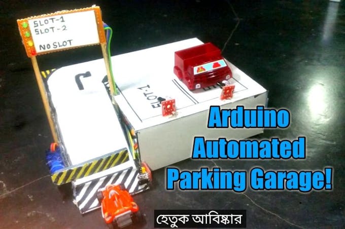
An Arduino Automated Car Parking System that is too easy and too fun to make. When a car arrives it shows the number of empty slots (if available) and then opens the gate. if there is not any empty slot then the gate does not open. Amazing thing is that the whole project can just be POWERED using a POWER BANK!!
Watch the video for the full tutorial.
Note: you can use display instead of my hand made led sign display.
Now lets get started.
Step 1: Parts
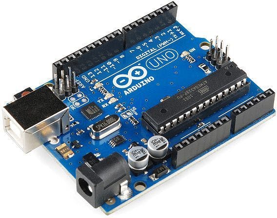
- Arduino - any board
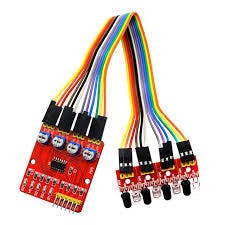
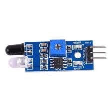
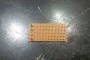
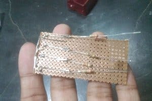
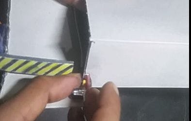
- Infrared proximmity sensor (pic 2 & 3 - both are functional)
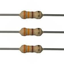
- 330r resistor
- some LED's
- Servo motor - any model or size you wish.
Step 2: Making the LED Display
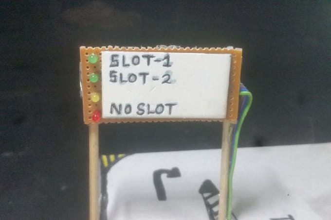
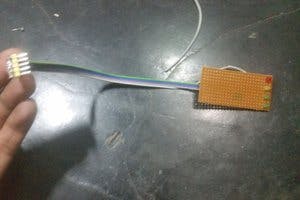
To make this LED display I have used a piece of bredboard then soldered the LED's and the 330r resistor. Then just added a ribbon cable for nice finish.
NOTE: I soldered the resistors on back so that they cant be seen from front to make the display.
It would be better if you use LCD display or cheap OLED display instead of this. I had not any, so I made this.
Step 3: Making the Parking Garage
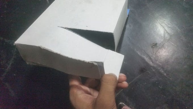

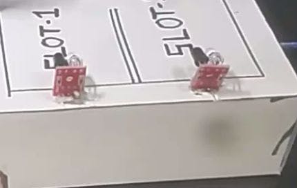
To make this I have used a card board box then cut it to make a nice slope. Then added a piece of cardboard on to the servo motor and hot glued it. Added one sensor on the entrance and another on each SLOT. Then hot glued two chopsticks with the display we have made and glue it to the box. And of course as we will use the usb cable of arduino to power the whole project cut some area of the box to access to that port.
Don't forget to paint it a little bit.
Step 4: The Circuit
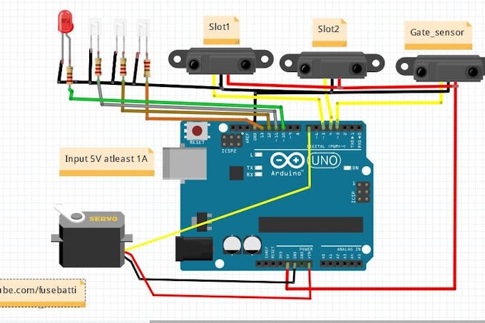
It looks a bit mess for the LED's but tell you what, this is really very much simple circuit.
NOTE: Proximity sensors use 5v to operate so you can just connect them to 5v source of arduino.
But what theee!! why has he connected servo to VIN!! Let me explain you. Power banks usually supplies 5v 1Amp current which is input to arduino via the usb cable, now there is a voltage regulator on arduino which gives.5Amp to the board. By connecting to VIN we are actually accessing the power from the power bank without an breadboard. This works and safe.
Step 5: The Code
Upload the following code to the arduino
download code https://github.com/ashraf-minhaj/Automated-Parking...
Update on 2nd Nov 2018: Version 2 : Version2 Code With LCD display downlaod from here
Update on 2nd Nov 2018: Version 2 : Version2 Code With LCD display downlaod from here
or copy CODE (version1) from below
Step 6: Finished
Now power the project using a USB cable to arduino and have fun.
Let me know how you are thinking to upgrade this and why.
Thank you.
Tq
ReplyDeleteMy pleasure.
Deletehow to enter the code
ReplyDeleteConnect your Arduino to pc by usb cable and Upload code using Arduino.ide
DeleteThanks.
how can use lcd display??
ReplyDeleteUse an I2C lcd, I've provided the code for it in the link.
DeleteHello, do u know how to set this up on the tinkercad simulator? both circuit and code?
DeleteYes, it is easy. Find the sensors from right side.
DeleteHello how do I go about if I want to include extra infrared sensor, and the code is showing error message for liquid crystal that no such directory
ReplyDelete//I2C display library
1. For adding more sensors you'd need to add them on code. Read from then and
Deleteadd on if statement like I did.
2. You need to install lcdi2c library for that to work with lcd.
Hello sir,I'm doing this project but unable to understand connections among aurdino, motor, led's and sensors even after going through blog and YouTube video. How can I get sort of this? Please help me with connections
ReplyDeleteyes same problem . i want detailed connections instructions.
Deletehello, could you please send me the circuit with the symbols? thanks my g
ReplyDeleteHow could you change the code if you are attaching camera and ultrasonic sensors? btw I subbed
ReplyDelete