Introduction
I've been trying to make a humanoid robot MOFIZA -Arduino Talking Humanoid Robot. recently- which means dealing with Servo motors. Everything worked just as fine just before I tried to make the robot TALK. When I needed to use the TMRpcm library. But there's some libraries like
#TMRpcm.h
#VirtualWire.h
are libraries that use the Timer1 of Arduino. It appears that you can't use two devices simultaneously where both use the same timer...So, if my robot talks- the servos don't work. Because The Servo.h and the TMRpcm both works on Arduino TImer1. Which is a mess. If you want to make both of them work you have to use another library for servos. Which is ServoTimer2 library? This uses the Timer2 on Arduino...Unfortunately on internet I haven't found any tutorials to understand how this ServoTimer2 library actually works, and how to use it in code. So, I've decided to make a tutorial so that people like me can understand better. We'll be using one servo motor with this library and make a simple Servo sweep code
You may watch the video to understand better.
Step 1: Parts & Assembly:
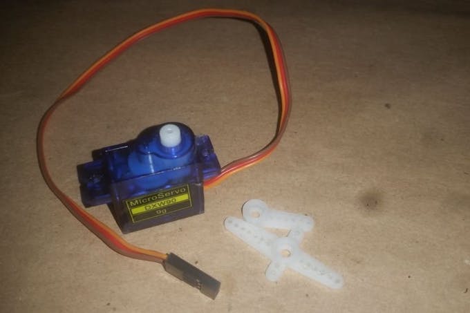


Main part is a Servo motor.
I'm using a micro servo sg90, any model is okay.
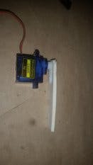
Then take a servo arm just like in pic2 and glue it on a hard cardboard (this is just to get a good visibility of degree) and then add the arm to the servo motor like in pic 4.
Step 2: Download and Add the ServoTimer2 Library to Arduino
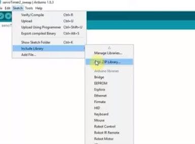
First of all, you'll have to download the library from here https://github.com/nabontra/ServoTimer2 and paste it to Arduino library folder.
Then go to sketch>include library>add zip.file from the library folder.
Now you're good to go.
Step 3: Build the Simple Circuit
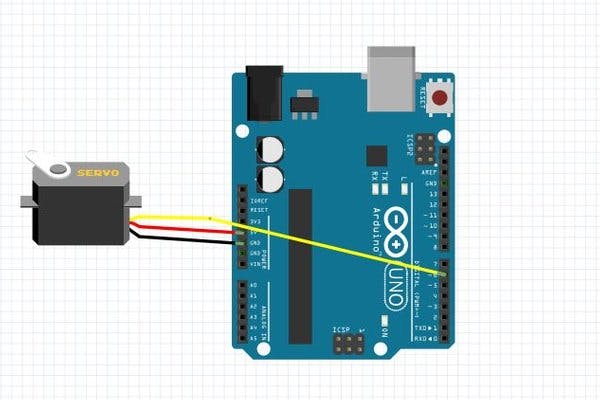
This is the most easy part
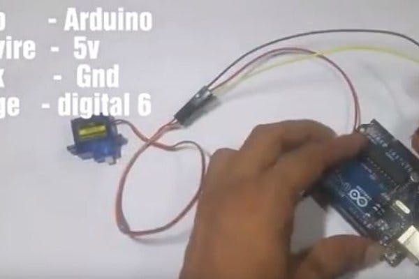
- Servo red wire to Arduino vcc (5v)
- grey - Gnd
- Orange- digital 6
NOTE: As we are using just a Servo without any load it is okay to power the servo from Arduino 5v. When you'll use the servo for other projects with more sensors an devices DO NOT power the Servo from Arduino 5v source. Nothing will burn,just the project wont run.
Step 4: The Code.
Before we get to know the ServoTimer2 code lets look back at Servo.h library sweep.
(the motor will rotate from 0 degree to 90 degree - wait for 1 sec- then to 180 degree-wait for 1 sec)
#include<Servo.h>
Servo servo1;
void setup()
{
servo1.attach(6);   // put your setup code here, to run once
}
void loop()
{  // put your main code here, to run repeatedly:
servo1.write(0);
delay(1000);
servo1.write(90);
delay(1000);
servo1.write(180);
delay(1000);
}
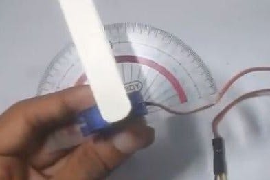
As you can see in this library if we wish to rotate a Servo to a certain position we had to just write the degree and the servo would do just fine. But in ServoTimer2 library we must write the Pulsewidth of the servo and the servo moves to that position using that. Most commonly 1500 means 90 degree. The maximum pulsewidth is 2250 and minimum is 750. Which would mean 750 is for 0 degree and 2250 is for 180 degree. But let me tell you, this varies from servo to servo. Just send in your values and see what happens. Don't worry this wont destroy or harm your servo motor a bit.
Now I'll make the same code for ServoTimer 2 and thus you'll get what actually the differences are.
#include"ServoTimer2.h"
ServoTimer2 servo1;
void setup()
{
servo1.attach(6);
}
void loop()
{                 // put your main code here, to run repeatedly:
servo1.write(750);  //min pulse width for 0 degree
delay(1000);
servo1.write(1500);  //pulse width for 90 degree
delay(1000);
servo1.write(2250);  //max pulse width for around 180 degree
delay(1000);
}
Now just power the arduino and see with a degree scale that for which value how much the servo rotate. And by doing this you can make your project go. Happy Making.o 2700 to get it done.
Step 5: Last-Power Up the Arduino and Experiment
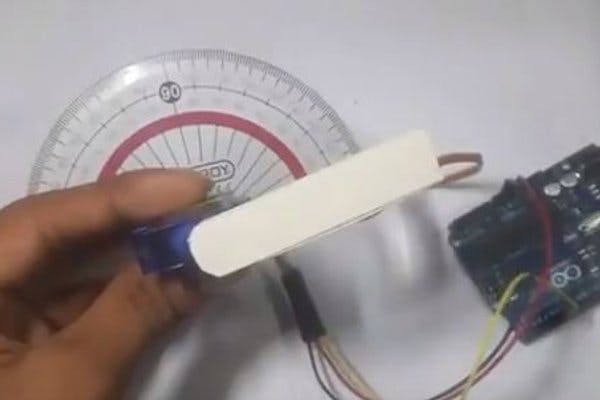
Now just power the arduino and see with a degree scale that for which value how much the servo rotate. And buy doing this you can make your project go. Happy Making.
Comments
Post a Comment