Making ROBOT ARMs is very popular and fun among hobbyists, but it's not that easy to control a ROBOT ARM. So today we'll be making a robot arm that can be controlled using just your Android Smartphone or tablet.
Good news is, you just need to program the Arduino, the App is already available to download for free.
Step 1: Parts You'll Need
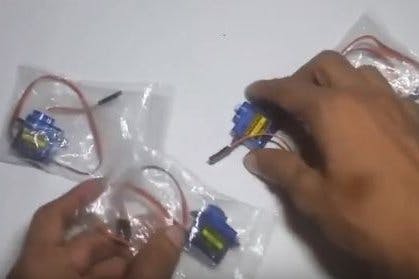
2 More Images
- Servo motor 4x (I'm using micro servo Sg90 but any model or size is okay) you can use upto 5 servo for this robot arm, I've only 4, so I'm using them.
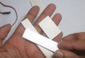
- sliced piece of Card Board - to make the body.
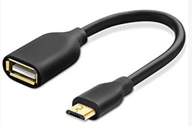
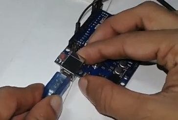
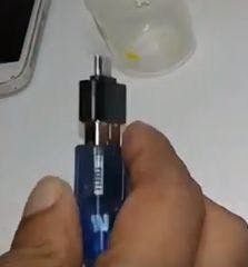
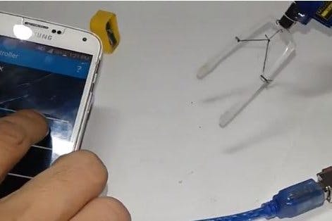
- USB OTG (on the go) [pic3 & 4- all the same]
- And of course a Arduino board (any board)
- And a few jumpers to make the connection
- And a 9v battery to power the servo motors.
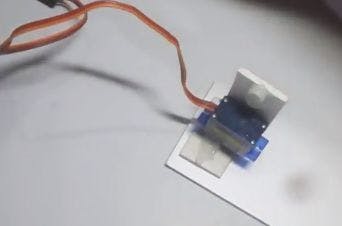
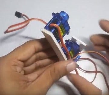
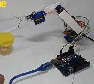
Step 2: Making the Robot Arm (THE BODY)
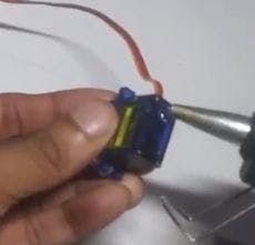
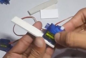
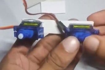
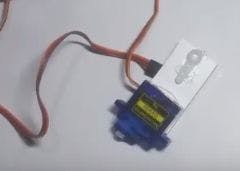
Now in here I'm actually making the body in a way so that I can easily connect and disconnect the ARM anytime. Using some pieces of cardboard and Hot glue I've mounted the Servo motors to the cardboard to make the body. It's better to watch the video to better understand how it's done.
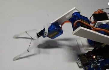
Step 3: Making the GRIPPER (finger for Robot Arm)
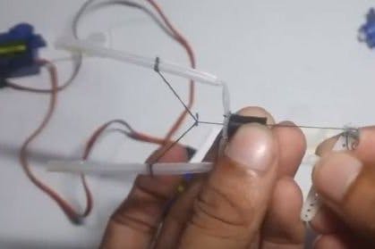
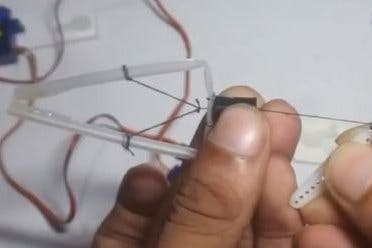
I've made the robot gripper using juice straw or pipe. And added a simple fiver or rope so that when it's pulled the grip will be closed.
Step 4: Assemble the Robot ARM
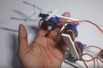
After making the arm and making & the gripper you just assemble the body as shown.
Step 5: The Circuit
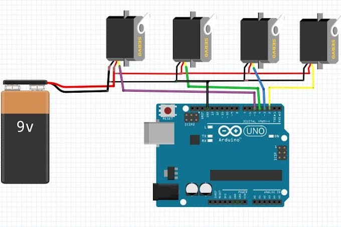
Well the circuit is very easy, you just need to power the servo motors. Arduino will take power from your phone via OTG cable. Don't worry, the power consumption is very low.
Step 6: Download the ANDROID APP
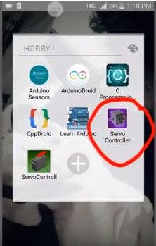
Search on google PLAYSTORE - Servo & Esc controller.
Download from here https://play.google.com/store/apps/details?id=com....
Then Install the app.
Step 7: Programming the Arduino
You can get the code from the link in the app, I'm providing the code below
# include <Servo.h>
//PWM OUTPUT VARIABLES
Servo pin2;
Servo pin3;
Servo pin4;
Servo pin5;
Servo pin6;
//SERIAL USB BUFFER
char inData[ 65 ]; // Allocate some space for the string
char inChar; // Where to store the character read
byte index = 0 ; // Index into array; where to store the character
void setup () {
//START PIN OUTPUT
pin2. attach ( 2); // attaches the servo on pin 9 to the servo object
pin3. attach ( 3);
pin4. attach ( 4);
pin5. attach ( 5);
pin6. attach ( 6);
//SEND MINIMAL VAUE 1000, REGUIRED FOR ESC TO ARM (max is 2000)
pin2. writeMicroseconds (1000 );
pin3. writeMicroseconds (1000 );
pin4. writeMicroseconds (1000 );
pin5. writeMicroseconds (1000 );
pin6. writeMicroseconds (1000 );
//INIT SERIAL COMMUNICATION WITH ANDROID
Serial. begin (115200 );
}
void loop () {
if (Serial. available () > 0 ){
//WAIT FOR INCOMMING DATA BUFFER TO FILL
if (index < 24){
inChar = Serial. read (); // Read a character
inData[ index ] = inChar; // Store it
index ++; // Increment where to write next
if (inChar == 'X' )
index = 0 ;
inData[ index ] = '\0' ; // Null terminate the string
}
}
if (index ==24 ){
index = 0;
//STRING LOOKS LIKE "A100B96C20D0E" WHERE LETTERS ACT AS DELIMINATOR
//STRING CAN CONTAIN SINGLE VALUE LIKE "B96C"
String buf = String (inData);
int ia = buf. indexOf ( "A", 0);
int ib = buf. indexOf ( "B", 0);
int ic = buf. indexOf ( "C", 0);
int id = buf. indexOf ( "D", 0);
int ie = buf. indexOf ( "E", 0);
int iff = buf. indexOf ("F" , 0 );
Serial. print ("|" );
//A?B
if (ia!=- 1 && ib!=- 1){
//1. CONVERT VALUE TO INTEGER
//2. CONVERT 0-100 TO 1000 - 2000
//3. WRITE TO ARDUINO PIN NUMBER 2
pin2. writeMicroseconds (map (buf. substring (ia+ 1, ib). toInt (), 1, 100 , 1000 , 2000 ));
//SEND RESPONSE TO ANDROID
Serial. print ( "RESPONSE:OK" );
}
//B?C
if (ib!=- 1 && ic!=- 1){
pin3. writeMicroseconds (map (buf. substring (ib+ 1, ic). toInt (), 1, 100 , 1000 , 2000 ));
//Serial.print("PIN3 OK");
}
//C?D
if (ic!=- 1 && id!=- 1){
pin4. writeMicroseconds (map (buf. substring (ic+ 1, id). toInt (), 1, 100 , 1000 , 2000 ));
//Serial.print("PIN4 OK");
}
//D?E
if (id!=- 1 && ie!=- 1){
pin5. writeMicroseconds (map (buf. substring (id+ 1, ie). toInt (), 1, 100 , 1000 , 2000 ));
//Serial.print("PIN5 OK");
}
//E?F
if (ie!=- 1 && iff!=- 1){
pin5. writeMicroseconds (map (buf. substring (ie+ 1, iff). toInt (), 1 , 100 , 1000 , 2000 ));
//Serial.print("PIN6 OK");
}
Serial. print ("|00" );
Serial. print ("\n" );
}
}
void logg (){
}
Okay download or copy the code from below.
Step 8: Connect the OTG and Arduino to Phone
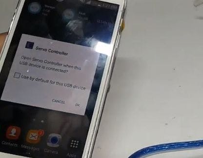
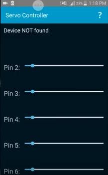
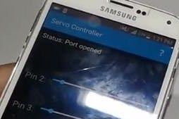
Connect the OTG cable to arduino programming (USB B) cable and then connect the wire with the phone. The APP will automatically pop up. Click on 'ok' and twill open. After connecting "port open" message will be seen.
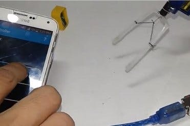
Step 9: Finished
And you're done, just power the Servo and use the app to rotate every single servo of the arm as you please. So Simple.
Thank you.
If you want to get my future projects time to time Subscribe via e-mail by clicking here
If you want to get my future projects time to time Subscribe via e-mail by clicking here
I'm glad it was helpful to you.
ReplyDeleteI can see your hardwork in this article, great work keep doing.
ReplyDeleteAWS Training in Chennai
DevOps Training in Chennai
android Training in Chennai
Android Course in Chennai
Java Training in Chennai
Thanks, you commented in my birthday anyway.
DeleteCan i use the 5v of the arduino for the servo source?
ReplyDeleteFor one servo it is okay but not recommended, You might harm the servo and Arduino. For a lot of servos, you cant. I powered them using a 5v 1A power bank then. But I recommend using at least 6v for these. Thanks.
DeleteWant report of this project urgently
ReplyDeleteI didn't write any report other than blog post.
DeletePlz make a video on wiring of the servo s and battery.plz
ReplyDeleteSure, I'll try to. Thank you.
DeleteGive me the circute diagram to make this project i give no send it to me 9360738976
ReplyDeleteEverything is given in this post!
DeleteBrother I want dimension of cardboard .
ReplyDeleteI just cut them randomly, make sure you cut pieces that fits your servo. That's it.
DeleteHow much cost and give the links of servos and Arduino please total how much cost
ReplyDeleteThey are very cheap, each servo costs 100 Taka (BDT) and Arduino costs around 400 Taka (BDT).
Deletehow u cable them plz
ReplyDeleteConnect the GND (black /gray) pins and VCC (red wire) to 6v/5v from a quality power bank and connect data pins to arduino 2,3,4,5,6
DeleteCan we use Arduino nano
ReplyDeleteShouldn’t be a problem
DeleteThis comment has been removed by the author.
ReplyDeletePlease send the project report bro
ReplyDeleteI'm sorry there is no project report, I did not write any other than this blog post. Thank you.
Delete