
Anti-theft Camera trigger with Arduino.


Ever wondered about making an anti-theft device with a camera trigger system? Or perhaps you want to make a device for your chocolate thief little brother which would just take picture when and if he takes the chocolate away...
To be clear, this post is all about controlling a smartphone camera via Arduino wirelessly. I'm just providing you the process to control the camera using Arduino. What you'll build using it is all up to you. The sky is the limit, right? Let's hop in guys.

Step 1: Parts You'll Need

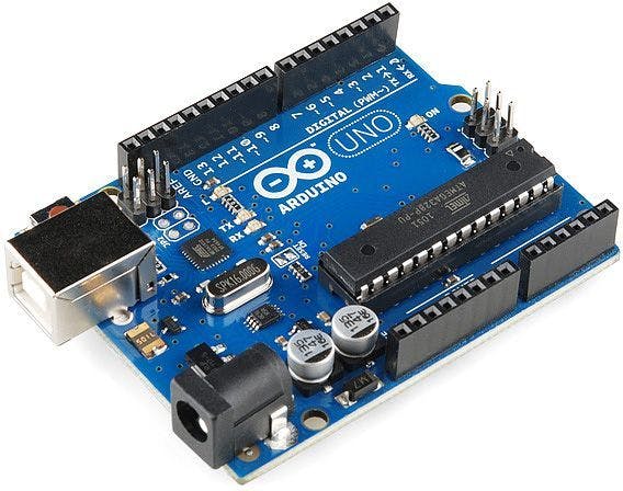
  • Arduino (Any development board you'd prefer)
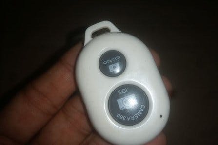
  • Selfie stick remote
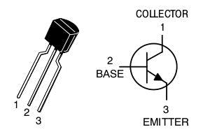
  • Any transistor // I've used BC547 NPN transistor

Step 2: Principle

Well the selfie stick remote controls phone camera using Bluetooth technology when a button is pressed. What we will do today is to trigger the switch anyway using Arduino.
So, we'll be using our transistor as what it was actually made to do- using it as a switch. we'll connect the BASE pin of a transistor to Arduino. And the emitter and collector will be attached to two points of the button of the remote.r
The working process:
Arduino will make The base pin HIGH so the the Collector & Emitter of Transistor will get connected and thus the button will get pressed virtually using arduino. Got it? lets proceed.

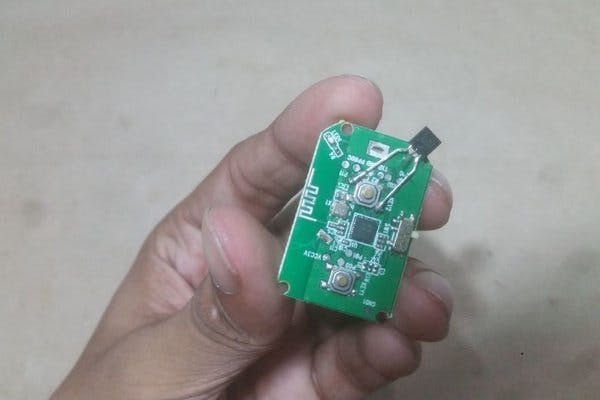
Step 3: Open the Cover and Take Out the Remote's PCB

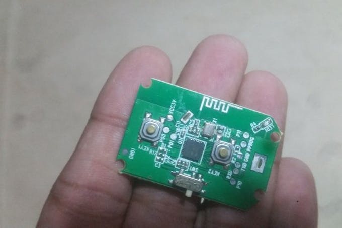
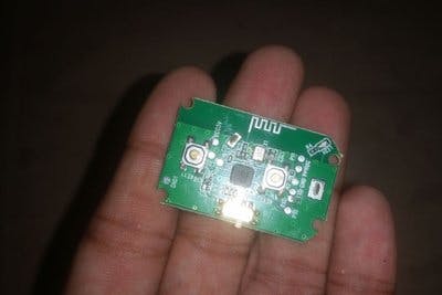
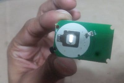
Carefully open the cover of the remote.
Remember which switch for which platform, there's two switches one for Android Phones, one for IOS. You would use the button / switch as your phones OS is.

Step 4: Build the Remote Circuit

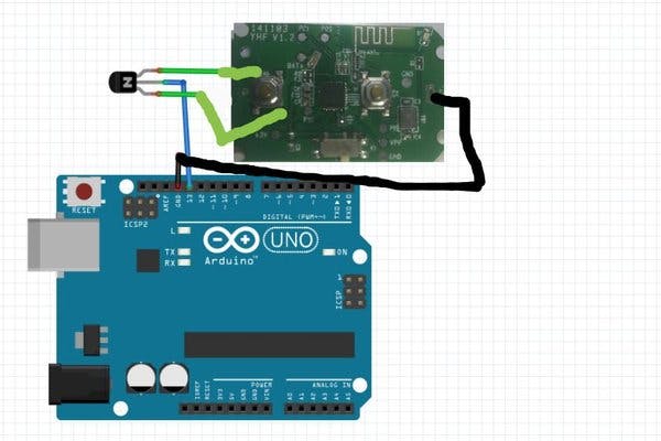
As I've mentioned earlier connect any transistors (my case BC547 NPN) emitter and collector to the buttons two end and the base to Arduino. Don't forget to connect the ground pin of remote with Arduino.
NOTE: I've powered the remote with its own battery. It's powered using a 3V button cell, as Arduino has 3.3V not 3V, so I didnt take the risk. That's why we need to common the ground pin.

Step 5: Application???

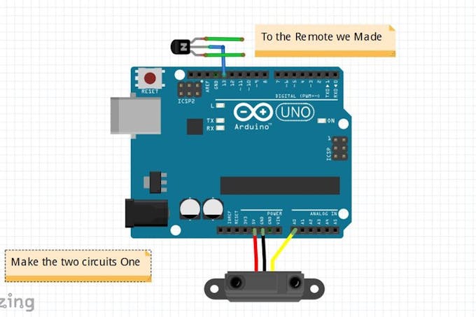
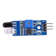
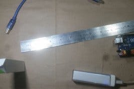
Man, you are done making this. This part is just two demonstrate how this can be used. So I've made an infrared proximity detector and motion camera trigger system. Remember: I've connected the output pin of proximity sensor to analog input 'A0' so that I get a high range and guess what? It worked for even 9 to 11 inches!
Code download: Camera Control by Arduino
Or copy from below:
/* Control any cell phone camera with Arduino Wirelessly******
  By Ashraf Minhaj. Find him at ashraf_minhaj@yahoo.com
 youTube channel www.youtube.com/c/fusebatti  */
/* This is a demo code with a proximity sensor on how to Trigger 
   the camera of your cell Phone by Arduino. You can make Ultrasound
   Motion sensor or PIR sensor to work as a Motion sensing anti theft 
   Camera system.
 *  It's just an Idea , The Sky is the Limit */
int trig = 13;
void setup() 
{
 pinMode(trig,OUTPUT);
 Serial.begin(9600);   // initialize serial communication at 9600 bits per second:
}
void loop()                // the loop routine runs over and over again forever:
{
   int sensorValue = analogRead(A0);     // read the input on analog pin 0:
 Serial.println(sensorValue);        // print out the value you read:
 delay(1);        // delay in between reads for stability
 if(sensorValue > 900)      //Something is detected/ object has been stolen
 {
   digitalWrite(trig,HIGH);  //trigger the camera
   delay(100);
   digitalWrite(trig,LOW);
   delay(1000);            // delay 1 sec_Take a picture in every second
 }
 else
 {
   digitalWrite(trig,LOW);
 }
}
Upload the code and see what happens.
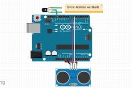
There's also a circuit using sonar sensor HC-SR04.
Again, I'm just giving you the idea... Let me know what you want to make using this in the comments section!

Comments

  1. anti theft using pir sensor i want to interface this to the camera

    ReplyDelete
    Replies
    1. Just make that pin high when PIR sensor is HIGH. As simple as that. You wont even need Arduino for that. PIR sensor can be used without Arduino too.

      Delete
  2. Ashraf - can u help with the idea - Setting the PIR sensor directly to Base of transistor - how would you make the base of transistor high when PIR is high? without using Arduino.

    ReplyDelete

Post a Comment

Popular posts from this blog

Make a Smart Phone Controlled Robotic Arm ! Arduino DIY.

Making ROBOT ARMs is very popular and fun among hobbyists, but it's not that easy to control a ROBOT ARM. So today we'll be making a robot arm that can be controlled using just your Android Smartphone or tablet. Good news is, you just need to program the Arduino, the App is already available to download for free. Step 1: Parts You'll Need 2 More Images Servo motor 4x (I'm using micro servo Sg90 but any model or size is okay) you can use upto 5 servo for this robot arm, I've only 4, so I'm using them. sliced piece of Card Board - to make the body. USB OTG (on the go) [pic3 & 4- all the same] And of course a Arduino board (any board) And a few jumpers to make the connection And a 9v battery to power the servo motors. Step 2: Making the Robot Arm (THE BODY) Now in here I'm actua

Make a Smart Humanoid Talking Robot- MOFIZA.

This Robot - Mofiza - (weird name) Can SEE , TALK and REACT to her surroundings. Before I proceed watch the video: Ever since I've seen making talking robots I saw that people actually use other development boards rather than Arduino to make talking robots. But it's completely possible to make a Humanoid robot with Arduino who can talk and add a lot of servos to make it move. So lets begin: Step 1: Parts You'll Need Arduino Pro mini (5v 16 Mhz) [any board is good but i've used this to make it small) Female header pins for connecting on pcb Male header pins Vero Board to make the circuit Sd card TF module (to make it talk) micro sd card (not more than 2GB) 3x IR proximity sensor 3x servo motor (I've used micro servo sg90) Cardboard to make the body Step 2: Connecting IR Sensor and the Body Make a

Make AI Assistant Robot with Arduino and Python

Introduction: We all are familiar with ‘Jarvis’ AI assistant robot from “Iron Man’ movies and Marvel series. It has always been a dream of programmers to make something on their own. I will today show a simple way to make such an assistant using Python programming. Moreover, I will also make a physical avatar of that robot, so that whenever we talk to the robot, it can do some movements. That will be more amazing than just a software robot. Because if it has a body, it is cool. So today we will learn to use both Arduino and Python programming to make an AI robot which can control your computer and have a little chit chat with you. Let’s hop in guys! Why I named the robot ‘Jaundice’? Because I painted it yellow, very very yellow!   Parts: Electronics - Arduino Nano – 1x Micro Servo Sg90 – 3x Ultra Sonic Sensor HCsr04 – 1x Body – PVC sheet (preferably white, better for coloring, I used blue one) Servo wheel (for the stand) Tools -  Cutter knife Scissor Hot glu

Arduino Automated Parking Garage

An Arduino Automated Car Parking System that is too easy and too fun to make. When a car arrives it shows the number of empty slots (if available) and then opens the gate. if there is not any empty slot then the gate does not open.  Amazing thing is that the whole project can just be POWERED using a POWER BANK!! Watch the video for the full tutorial. Note: you can use display instead of my hand made led sign display. Now lets get started. Step 1: Parts Arduino  - any board Infrared proximmity sensor  (pic 2 & 3 - both are functional) 330r resistor some  LED 's Servo motor  - any model or size you wish. Step 2: Making the LED Display To make this  LED display  I have used a piece of bredboard then soldered the LED's and the 330r resistor. Then just added a ribbon cable f

Problems using PIR sensor?? Always HIGH? DELAY? Solution is here.

PIR sensor When I was working on a project "controlling home appliances using just a wave of hand" I had used a PIR sensor and found some issues: PIR doesn't work properly when starts. PIR output value is always 1. It some times doesn't read motions. Now those are three Common and Unavoidable problems of a PIR sensor. So what would we do? I assume you know what a PIR sensor is and I'll just try to give a solution to the problems so that you can use PIR in your project efficiently, also I've added a code below on how to solve that problem. As I have mentioned earlier those are Common and Unavoidable,  keep 3 issues in mind: After powering - PIR sensor needs 1 minute to function For that 1 minute the OUTPUT is always HIGH. When a motion is detected it'll take 5 to 7 seconds to detect motion again. SOLUTION: After powering - PIR sensor needs 1 minute to function:  which means when you'll power a PIR sensor it wi

Control Anything Over Internet / WiFi. IOT Light Switch_ NodeMCU ESP8266 .

Parts: NodeMCU ESP8266  WiFi Development Board LED 330r resistor Android app Download the app from Below , To Upload code to NodeMCU using Arduino.ide Update Arduino.ide (desktop app) start Arduino app goto  Files > Preferences  Then  paste the link  then press  ok.    http://arduino.esp8266.com/stable/package_esp8266com_index.json goto  Tools>Boards> Board Manager  then wait untill it finds ESP8266 properties Scroll down and  click install Then Restart the Arduino App. Now you can upload Code in C / C++ to NodeMCU ESP8266 using Arduino.ide Getting IP Address Code T o get the IP Address (Internet Protocol Address) Upload this Code and open serial monitor. #include <ESP8266WiFi.h> const char* ssid="WIFI name"; const char* password = "WIFI PASSWORD"; int ledPin = 13; void setup() { pinMode(ledPin,OUTPUT); digitalWrite(ledPin,LOW); Serial.begin(115200); Serial.println(); Serial.print("Wifi co

How to use ServoTimer2 Library with Arduino- full tutorial.

Introduction I've been trying to make a humanoid robot  MOFIZA -Arduino Talking Humanoid Robot.  recently- which means dealing with Servo motors. Everything worked just as fine just before I tried to make the robot TALK. When I needed to use the TMRpcm library. But there's some libraries like #TMRpcm .h #VirtualWire .h are libraries that use the Timer1 of Arduino. It appears that you can't use two devices simultaneously where both use the same timer...So, if my robot talks- the servos don't work. Because The Servo.h and the TMRpcm both works on Arduino TImer1. Which is a mess. If you want to make both of them work you have to use another library for servos. Which is ServoTimer2 library? This uses the Timer2 on Arduino...Unfortunately on internet I haven't found any tutorials to understand how this ServoTimer2 library actually works, and how to use it in code. So, I've decided to make a tutorial so that people like me can understand better. We'll be u