
Arduino Voice Controlled Robot!

 Robots are cool. To have a robot that can move around listening to your voice commands is more cool. To make such a Speech or Voice controlled robot with Arduino is more more and more cool. Because Arduino's are cheap and easy to tweak.

Let's start making, you can also watch the video tutorial.

Step 1: Parts Needed

The robot is based on PCB. A PCB I designed to use in different robots. Let's see what other components I used -
Electronics:
  • Arduino Nano - 1x
  • L298n Motor Driver module - 1x
  • Hc05 Bluetooth module - 1x
  • DC motor and compatible wheel - 2x
  • Multifunctional Robot PCB - 1x (link)
  • Some male and female headers
To Make Body:
  • PVC Sheet
  • Hot Glue Gun
Software:
  • Arduino.ide
  • An App that I made
That's it, now we are good to go.

Step 2: Principle: How Will It Work?

It's always good to have a clear understanding of what you're going to do before starting to actually messing things. May be you don't mess, but I do.
So, Arduino is a mini computer or say, microcontroller. It doesn't have enough power or capability to perform speech recognition (as of now). But lucky for me, my PCB board has a port to connect Bluetooth module. Means, I can connect our Arduino wirelessly to other devices. And I'm taking advantage of that thing. So, I will have to make an Android app that can perform "Speech to Text" operation using google API (requires internet) and after receiving the text, it will command Arduino over Bluetooth.
So, If I say 'Forward' the robot will get 'F' and will move forward. That's the concept. Now let's make it.

Step 3: Make the Body

I made the chassis/body of this robot from a 13cm/13.5cm PVC sheet. It's easier to cut using a blade/knife and works great with glues too.
As you can see in the video, I cut pieces to mount two motors and wheels both inside the board area. And then glued them.
When you will make yours, you don't need to make it look exactly like this. Your bot your choice.

Step 4: Build Circuit or Use PCB?

Here again we come to point where it's completely your choice. But, to make a circuit like this one requires bunch of wiring, and if you make it using bread-board one misconnection can hamper the whole project. That's why I like to use PCB's in my projects.
I designed this PCB using EasyEDA and ordered it from PCBWay.com . PCBWay provides quality at a cheaper rate. You can get 10 multi-layer PCB with just 5$. They also sponsor student projects which feels great to me.
Anyway, I went to Quick Order section where all I needed to do is upload my PCB, the system automatically detected all the parameters for my board and I just selected colors. Black is my favorite and look how shiny and cool it turned out. It's better because they don't take money until their engineering team inspects your PCB, well enough!
Get the PCB board from here.
However, if you can't order or use this PCB, you can do it on bread board or vero board. I have uploaded the fritzing circuit for you. Download it from below or get it from here.

Step 5: Connect Electronics


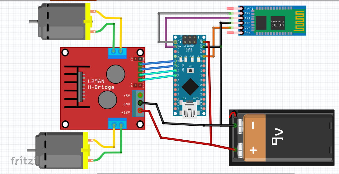
Connection is straight forward. Connect all things as shown in the circuit diagram. I'll start from connecting motors to motor driver -
Motor to motor driver,
  • Motor1 wires goes to one end of driver,
  • Motor2 goes to other end.
To control the motors,
  • Motor1 pins on L298n motor driver connect to Arduino 2 and 3 pins (digital).
  • Motor2 connects on 4 and 5
Bluetooth module,
  • Tx to Arduino Rx
  • Rx to TX
  • VCC to 5V/VCC
  • Gnd to GND (Ground)
Battery,
I used 7.4V battery for the motors, that connects to motor driver input and Arduino VIN and Ground Pin. Common ground connection is needed.
Then I connected the battery in all the things lit up. Means, I did no mistake.

Step 6: Programming Arduino

It's a simple program. The program checks for characters and if they are received it goes left right etc. The list is -
  • 'F' - Forward
  • 'B' - Backward
  • 'L' - Left
  • 'R' - Right
The Bluetooth module is connected on serial port, so Arduino is communicating over serial in 9600 bps.
I setup section I defined the pins and buad rate -
void setup()
{
//initlize the mode of the pins
pinMode(lm1,OUTPUT);
pinMode(lm2,OUTPUT);
pinMode(rm1,OUTPUT);
pinMode(rm2,OUTPUT);
//set the serial communication rate
Serial.begin(9600);
}
The in mainloop It checked for data received over serial-
//check whether arduino is reciving signal or not
while(Serial.available() == 0);
val = Serial.read() ; //reads the signal
Serial.print(val);
And then the main code, download it from here. I pasted whole code below -
/**** Arduino Speech/voice Controlled robot ***
* by Ashraf Minhaj
* mail me at ashraf_minhaj@yahoo.com
* tutorial- ashrafminhajfb.blogspot.com
*/
//Declare the arduino pins
int lm1 = 4; //declare 1st motor pins
int lm2 = 5;
int rm1 = 2; //right motor pins
int rm2 = 3;
char val;
void setup()
{
//initlize the mode of the pins
pinMode(lm1,OUTPUT);
pinMode(lm2,OUTPUT);
pinMode(rm1,OUTPUT);
pinMode(rm2,OUTPUT);
//set the serial communication rate
Serial.begin(9600);
}
void loop()
{
//check whether arduino is reciving signal or not
while(Serial.available() == 0);
val = Serial.read() ; //reads the signal
//Serial.print(val);
/*********For Forward motion*********/
if (val == 'F')
{
//Serial.println("FORWARD");
digitalWrite(lm1,HIGH);
digitalWrite(rm1,HIGH);
digitalWrite(lm2,LOW);
digitalWrite(rm2,LOW);
}

/*********For Backward Motion*********/
else if(val == 'B')
{
digitalWrite(lm2,HIGH);
digitalWrite(rm2,HIGH);
digitalWrite(lm1,LOW);
digitalWrite(rm1,LOW);
}

/*********Right*********/
else if(val == 'R')
{
digitalWrite(lm1,HIGH);
digitalWrite(rm2,HIGH);
digitalWrite(lm2,LOW);
digitalWrite(rm1,LOW);
}

/*********Left*********/
else if(val == 'L')
{
digitalWrite(lm2,HIGH);
digitalWrite(rm1,HIGH);
digitalWrite(lm1,LOW);
digitalWrite(rm2,LOW);
}
/*********STOP*********/
else
{
digitalWrite(lm1,LOW);
digitalWrite(rm1,LOW);
digitalWrite(lm2,LOW);
digitalWrite(rm2,LOW);
}
delay(10);

}
Upload the code and then make the app.
Note: With just this code your robot will become a Bluetooth controlled bot, you can now control it using apps or from your PC.

Step 7: App for SPEECH to TEXT

I made the app using MIT app inventor. You can edit and customize this app as your requirements. Get the aia fie from here.
This app uses Bluetooth connectivity to control the robot. For that I needed to pair HC05 Bluetooth module to my phone. The default password is either 1234 or 0000.
This app uses google Speech to Text API to convert what I say into text form. Then it makes the sentence into lower case, it's easier to process that way. And matches using if else statements. If user says 'forward' send Arduono the 'F' letter and it will go forward. That's it.
Build and save as APK file, or use mine install it on your phone.

Step 8: Power the Bot, Run App and Go!

Now just plug in the battery, and use the Android app to play around with your brand new robot!
Thank you for reading.

Comments

Popular posts from this blog

Make a Smart Phone Controlled Robotic Arm ! Arduino DIY.

Making ROBOT ARMs is very popular and fun among hobbyists, but it's not that easy to control a ROBOT ARM. So today we'll be making a robot arm that can be controlled using just your Android Smartphone or tablet. Good news is, you just need to program the Arduino, the App is already available to download for free. Step 1: Parts You'll Need 2 More Images Servo motor 4x (I'm using micro servo Sg90 but any model or size is okay) you can use upto 5 servo for this robot arm, I've only 4, so I'm using them. sliced piece of Card Board - to make the body. USB OTG (on the go) [pic3 & 4- all the same] And of course a Arduino board (any board) And a few jumpers to make the connection And a 9v battery to power the servo motors. Step 2: Making the Robot Arm (THE BODY) Now in here I'm actua

Make a Smart Humanoid Talking Robot- MOFIZA.

This Robot - Mofiza - (weird name) Can SEE , TALK and REACT to her surroundings. Before I proceed watch the video: Ever since I've seen making talking robots I saw that people actually use other development boards rather than Arduino to make talking robots. But it's completely possible to make a Humanoid robot with Arduino who can talk and add a lot of servos to make it move. So lets begin: Step 1: Parts You'll Need Arduino Pro mini (5v 16 Mhz) [any board is good but i've used this to make it small) Female header pins for connecting on pcb Male header pins Vero Board to make the circuit Sd card TF module (to make it talk) micro sd card (not more than 2GB) 3x IR proximity sensor 3x servo motor (I've used micro servo sg90) Cardboard to make the body Step 2: Connecting IR Sensor and the Body Make a

Make AI Assistant Robot with Arduino and Python

Introduction: We all are familiar with ‘Jarvis’ AI assistant robot from “Iron Man’ movies and Marvel series. It has always been a dream of programmers to make something on their own. I will today show a simple way to make such an assistant using Python programming. Moreover, I will also make a physical avatar of that robot, so that whenever we talk to the robot, it can do some movements. That will be more amazing than just a software robot. Because if it has a body, it is cool. So today we will learn to use both Arduino and Python programming to make an AI robot which can control your computer and have a little chit chat with you. Let’s hop in guys! Why I named the robot ‘Jaundice’? Because I painted it yellow, very very yellow!   Parts: Electronics - Arduino Nano – 1x Micro Servo Sg90 – 3x Ultra Sonic Sensor HCsr04 – 1x Body – PVC sheet (preferably white, better for coloring, I used blue one) Servo wheel (for the stand) Tools -  Cutter knife Scissor Hot glu

Arduino Automated Parking Garage

An Arduino Automated Car Parking System that is too easy and too fun to make. When a car arrives it shows the number of empty slots (if available) and then opens the gate. if there is not any empty slot then the gate does not open.  Amazing thing is that the whole project can just be POWERED using a POWER BANK!! Watch the video for the full tutorial. Note: you can use display instead of my hand made led sign display. Now lets get started. Step 1: Parts Arduino  - any board Infrared proximmity sensor  (pic 2 & 3 - both are functional) 330r resistor some  LED 's Servo motor  - any model or size you wish. Step 2: Making the LED Display To make this  LED display  I have used a piece of bredboard then soldered the LED's and the 330r resistor. Then just added a ribbon cable f

Problems using PIR sensor?? Always HIGH? DELAY? Solution is here.

PIR sensor When I was working on a project "controlling home appliances using just a wave of hand" I had used a PIR sensor and found some issues: PIR doesn't work properly when starts. PIR output value is always 1. It some times doesn't read motions. Now those are three Common and Unavoidable problems of a PIR sensor. So what would we do? I assume you know what a PIR sensor is and I'll just try to give a solution to the problems so that you can use PIR in your project efficiently, also I've added a code below on how to solve that problem. As I have mentioned earlier those are Common and Unavoidable,  keep 3 issues in mind: After powering - PIR sensor needs 1 minute to function For that 1 minute the OUTPUT is always HIGH. When a motion is detected it'll take 5 to 7 seconds to detect motion again. SOLUTION: After powering - PIR sensor needs 1 minute to function:  which means when you'll power a PIR sensor it wi

Control Anything Over Internet / WiFi. IOT Light Switch_ NodeMCU ESP8266 .

Parts: NodeMCU ESP8266  WiFi Development Board LED 330r resistor Android app Download the app from Below , To Upload code to NodeMCU using Arduino.ide Update Arduino.ide (desktop app) start Arduino app goto  Files > Preferences  Then  paste the link  then press  ok.    http://arduino.esp8266.com/stable/package_esp8266com_index.json goto  Tools>Boards> Board Manager  then wait untill it finds ESP8266 properties Scroll down and  click install Then Restart the Arduino App. Now you can upload Code in C / C++ to NodeMCU ESP8266 using Arduino.ide Getting IP Address Code T o get the IP Address (Internet Protocol Address) Upload this Code and open serial monitor. #include <ESP8266WiFi.h> const char* ssid="WIFI name"; const char* password = "WIFI PASSWORD"; int ledPin = 13; void setup() { pinMode(ledPin,OUTPUT); digitalWrite(ledPin,LOW); Serial.begin(115200); Serial.println(); Serial.print("Wifi co

How to use ServoTimer2 Library with Arduino- full tutorial.

Introduction I've been trying to make a humanoid robot  MOFIZA -Arduino Talking Humanoid Robot.  recently- which means dealing with Servo motors. Everything worked just as fine just before I tried to make the robot TALK. When I needed to use the TMRpcm library. But there's some libraries like #TMRpcm .h #VirtualWire .h are libraries that use the Timer1 of Arduino. It appears that you can't use two devices simultaneously where both use the same timer...So, if my robot talks- the servos don't work. Because The Servo.h and the TMRpcm both works on Arduino TImer1. Which is a mess. If you want to make both of them work you have to use another library for servos. Which is ServoTimer2 library? This uses the Timer2 on Arduino...Unfortunately on internet I haven't found any tutorials to understand how this ServoTimer2 library actually works, and how to use it in code. So, I've decided to make a tutorial so that people like me can understand better. We'll be u