Wireless Mood Meter
Suppose your mood changes so fast that people can't cope up with it. You feel sad but people do something that makes you more sad. If only they knew what you are feeling right now!Behold, I present you the Wireless Mood Swing Meter!! Place it where everyone can see it, tap on your phone and input how you feel, the meter dial will point to an emoji and show others what you feel. Now people will behave accordingly.
Wanna make one? Let's start. Watch the video alongside.
Step 1: Parts You'll Need
Electronics:
- Arduino Nano (Any board will do) -1x
- HC05 Bluetooth module -1x
- Micro Servo sg90 -1x
- Powerbank or 5v 1 Amp power source - 1x
Others -
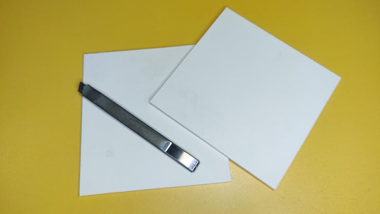
- PVC sheet - 1 piece
- Hot Glue and Glue Gun
- Mood meter (paper printable)
Step 2: Principle: How Will It Work?
Good questions lead to good answer. Before making anything you must have a clear understanding of what you are going to do.
So, the idea is, we will make a mood meter with emojis indicating my emotions. A little dial which will be attached by a servo will move and point at certain emoji based on my input on mobile phone.
So we will have to make a wireless circuit and Android application to make it work. Got it? Now, let's start.
Step 3: Cut Glue, Cut and Glue
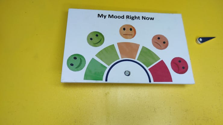
print the 'mood meter.pdf' file, then cut mood meter and dial accordingly. After that glue them on PVC sheet. You can also use hardboard/cardboard instead of PVC sheet. After that glue a servo arm on the dial and complete the whole thing.
I designed this thing. But you can use your own thing. Download the paper printable file from below.
While attaching the dial/servo arm with the main board, make sure the servo motor runs 180 degree and the path of the dial falls into that.
Step 4: Circuit Diagram and PCB
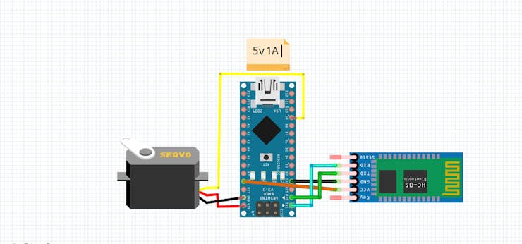
The circuit is pretty easy. The major components are Arduino, Servo and Bluetooth module.
Connect them as follows:
- Servo data pin to Arduino 9
- Servo VCC to Vin and gnd to gnd
- Bluetooth rx to Arduino tx
- Bluetooth tx to Arduino rx
All the things became easy because I used PCB. I designed this multipurpose robot PCB so that I can make multiple robots without worrying much about wires. I designed the PCB usign EasyEDA and printed from PCBWay.com. Their service is one of the best that's why I love to print from them. With 5$ you can get 10 multilayer PCB. I went to PCB instant Quote Quick Order and uploaded the files The system automatically detected all the necessary parameters. I just picked color.
I also have uploaded circuit diagram below if you don't want to use PCB at all.
Step 5: Code for the Project
This program is written in Arduino. It's simple enough to understand for all.
I imported servo library to control servo, declared a variable to store received value.
#include<Servo.h>
// declare servo name
Servo meter_servo;
// we'll store input data in this variable
char val;
In setup function the connected servo to pin 9, Bluetooth module is connected on serial port of Arduino with buad rate 9600.
void setup()
{
//initlize the mode of the pins
meter_servo.attach(9);
//set the serial communication rate with bluetooth module
Serial.begin(9600);
}
In main loop I check if any data is received -
while(Serial.available() == 0); //check whether arduino is reciving signal or not
val = Serial.read() ;           //read data sent over bluetooth
If any data is received it moves the servo to a certain position, if it receives
- 'h' - moves to happy emoji
- 'm' - medium happy emoji
- 'n' - neutral emoji
- 's' - sad emoji
- 'a' - angry emoji
Example for happy -
/********* Happy *********/
if (val == 'h'){
meter_servo.write(180);
}
Now here's the full code. Download from github or copy from below. I recommend downloading to avoid errors.
/**** Wireless Mood Meter ***/
/*  author   : Ashraf Minhaj
*  mail     : ashraf_minhaj@yahoo.com
*  tutorial : youtube.com/fusebatti
*/
#include<Servo.h>
// declare servo name
Servo meter_servo;
// we'll store input data in this variable
char val;
void setup()
{
//initlize the mode of the pins
meter_servo.attach(9);
//set the serial communication rate with bluetooth module
Serial.begin(9600);
}
void loop()
{
while(Serial.available() == 0); //check whether arduino is reciving signal or not
val = Serial.read() ;           //read data sent over bluetooth
/********* Happy *********/
if (val == 'h'){
meter_servo.write(180);
}
/********* Medium Happy ***/
if (val == 'm'){
meter_servo.write(130);
}
/********* Neutral *******/
if (val == 'n'){
meter_servo.write(70);
}
/********* Sad *******/
if (val == 's'){
meter_servo.write(20);
}
/********* Angry *******/
if (val == 'a'){
meter_servo.write(0);
}
}
Upload the program and move on to next step.
Step 6: Mood Meter Controller App
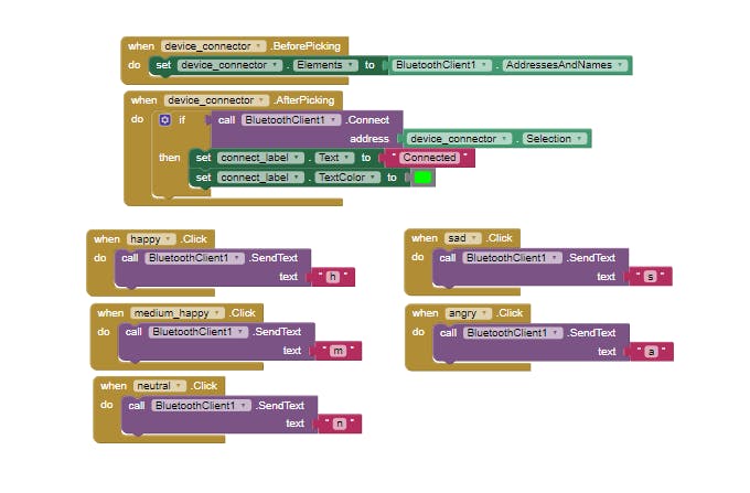
In order to send commands to the Mood Meter I made an android application. Which actually does connect with the board using Bluetooth connection and sends data it is supposed to send.
- ''h'
- 'm'
- 'n'
- 's'
- 'a'
You just need to click on an emoji and the data will be sent to Arduino.
I made the application using MIT app inventor2. It's simple and drag and drop coding makes it more cool. See pictures, the code is also very little. It looks for available paired devices and sends data over Bluetooth. Download the app from below or click here to get the.aia file and edit yourself.
Step 7: Power Up and GO!
Now power it up using powerbank, connect Bluetooth module to your phone. Default password is '0000' or '1234'. Open mood meter controller app and click 'connect with meter' button. A list picker will appear, select your module and then just click on emojis, it will work like a charm.
Thank you everyone for reading. A little thumbs up will be a lot. Happy Making!!!
It's time to say hello my dear.
ReplyDelete